2022年6月29日星期三

Do You Really Know Butterfly Valve?

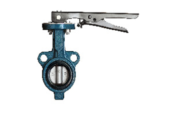
A butterfly valve, as the name suggests, whose key parts like a butterfly against the wind, free rotation. The butterfly valve disc is the disc, around the seat of a shaft rotation, the size of the angle of rotation is the valve open and close.

1.Butterfly valve construction

The butterfly valve is mainly composed of a valve body, living body, valve shaft, bearing, sealing device, operating mechanism, and accessories.

2.How butterfly valves work

The butterfly valve is according to rotate the valve stem drive disc rotating at the same time for opening and closing of a valve, cylindrical channels in the butterfly valve body, disc around the axis of rotation, mainly is 90 ° rotating disc for flow control, when the butterfly plate reaches 90 ° valves in the fully open position, at the same time can change the angle of the butterfly plate to adjust the medium flow rate, generally installed on the diameter of the pipe direction. Butterfly valve and stem themselves are not capable of locking, in order to effectively regulate the flow need to install worm gear reducer, the butterfly valve equipped with worm gear reducer not only makes the butterfly valve self-locking ability but also can change the operating performance of butterfly valve and more accurate regulation of medium flow.

1)Butterfly valve has small flow resistance when fully opened. When opened at about 15°-70°, and can be sensitive flow control, thus in the field of large-diameter regulation, the butterfly valve is a very common application. Most butterfly valves can be used in media with suspended solid particles because the disc movement is scrubbing. Depending on the strength of the seal, it can also be used for powder and granular media.

2)Butterfly valve is suitable for flow regulation. The butterfly valve in the pipe pressure loss is relatively large, about three times as much as the gate valve, so when choosing butterfly valve, the pipeline system should be fully considered by the impact of pressure loss, should also consider the butterfly plate under the pressure of the pipeline medium strength. In addition, consideration must be given to operating temperature limitations of resilient seat materials at high temperatures.

3)The structure length and overall height of the butterfly valve are small, opening and closing speed is fast, and has good fluid control characteristics. The butterfly valve structure principle is most suitable for the manufacture of large diameter valves. When butterfly valves are required for flow control, the most important thing is to correctly select the specifications and types of butterfly valves so that they can work properly and effectively.

Do You Really Know Butterfly Valve?

3.History

Butterfly valves have been in use since the end of the 18th century. James Watt used a butterfly valve in his steam engine prototype. With advances in materials and technology, butterfly valves can be made smaller and can withstand higher temperatures. After World War II, synthetic rubber was used for seals, allowing butterfly valves to be used in more industries. In 1969, James E. Hemphill patented an improvement in the butterfly valve that reduced the hydrodynamic torque required to change the valve's output.

We are Casting Valve Manufacturer. If you are interested in our products, please feel free to contact us.

2022年6月24日星期五

Several Taboos for Installing Valves

Installing a valve is not an easy task. There are 4 taboos, do you know all of them? If these taboos are violated, what are the consequences? How to solve it? China Cast Iron Check Valve supplier will tell you.


1.During winter construction, a water pressure test is carried out at a negative temperature.

Consequence: As the tube freezes quickly during the hydraulic test, the tube freezes.

Measures: Try to carry out a hydraulic test before the winter application, and blow off the water after the pressure test, especially the water in the valve must be cleaned, otherwise the valve will freeze and crack.

When the water pressure test is carried out in winter, the project must be carried out at a positive indoor temperature, and the water must be blown off after the pressure test. When the water pressure test cannot be carried out, the test can be carried out with compressed air.


2. The valve installation method is wrong.

For example, the water (vapor) flow direction of the Globe Valve or check valve is opposite to the sign, the valve stem is installed downwards, the horizontally installed check valve is installed vertically, the open-stem gate valve or butterfly valve handle has no open or closed space, and the valve stem is hidden. Do not face the inspection door.

 Consequences: The valve fails, the switch is difficult to repair, and the valve stem faces down often causing water leakage.

Measures: Strictly install according to the valve installation instructions. The rising stem gate valve should leave enough stem to extend the opening height. The butterfly valve fully considers the handle rotation space. Various valve stems cannot be lower than the horizontal position, let alone downward. The concealed valve should not only be equipped with an inspection door that meets the needs of valve opening and closing but also the valve stem should face the inspection door.


3. The specifications and models of the installed valve do not meet the design requirements.

For example, the nominal pressure of the valve is less than the system test pressure; the water supply branch pipe adopts a gate valve when the pipe diameter is less than or equal to 50mm; the dry and standpipe of the hot water heating adopts a stop valve; the fire water pump suction pipe adopts a butterfly valve.

Consequences: Affect the normal opening and closing of the valve and the adjustment of resistance and pressure. Even during the operation of the system, the valve is damaged and forced to be repaired.

Measures: Familiarize with the application scope of various valves, and select valve specifications and models according to design requirements. The nominal pressure of the valve must meet the requirements of the system test pressure. According to the requirements of the construction specification: the water supply branch pipe diameter is less than or equal to 50mm should use a stop valve; when the pipe diameter is greater than 50mm, a gate valve should be used. Gate valves should be used for hot water heating dry and vertical control valves, and butterfly valves should not be used for fire-fighting pump suction pipes.

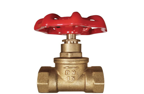
Brass gate valve

4.The pipeline system was not flushed carefully before completion, and the flow rate and speed did not meet the pipeline flushing requirements. It even replaces flushing with a water pressure strength test.

Consequences: The water quality does not meet the operating requirements of the pipeline system, which often results in the reduction or blockage of the pipeline section.

Measures: Use the maximum set juice flow rate in the system or a water flow rate not less than 3m/s for flushing. The watercolor and transparency of the discharge outlet should be consistent with the watercolor and transparency of the inlet water visually as qualified.


2022年6月20日星期一

Check Valve Maintenance Guide


Cast Steel Check Valve

Have you checked the cast steel check valve recently? They need to be carefully maintained to ensure that fluids flow safely and prevent spills. Damage or wear can cause many problems. What systems do you have to ensure "healthy" check valves? We have simple guidelines for maintaining them.


Why are check valves important?


What is the purpose of the check valve? If you need fluid to flow through a pipe in one direction, you can't do without them. Check valves are designed with a two-way system with openings that allow fluid to pass through. After the flow has passed, the valve closes to prevent backflow. Check valves can also close automatically if downstream pressure is excessive.


Common uses of check valves:


  • Water and waste pumping systems

  • Water pipe

  • Sewage treatment system

  • Heating system

  • Fire hose

  • Marine and naval industries

  • Oil and gas pipelines

  • Flush toilet device

There are many different types of check valves, including rotary check, lift check, piston check, and ball check.


Maintain check valves


Gost Check Valve doesn't require much maintenance. They can last for years. However, if debris or other foreign matter gets stuck between the ball and seat, they may leak and reduce the check valve function.


Step 1: Keep it clean


Take action to keep the area clean to prevent damage to the check valve. If the valve can be reached, only a towel is needed to wipe off the dust and dirt. If crumbs clump, use a wire brush.

Step 2: Stay alert

Another simple trick is to check the equipment regularly. This is a great way to spot potential problems before you end up needing expensive repairs.

Check valve inspection:

Leak check

Look for signs of corrosion, rust, or mineral accumulation

Replace valve if there are large amounts of leaking or worn/damaged parts

Open and close valves to ensure they are not stuck

Check the pressure and temperature of the fluid passing through

Make sure they do not close or exceed the valve's rated limit

Note: Ensure that high pressure and high-pressure valves are monitored more frequently.


Step 3: Clean up everything


You will need to remove and remove the valve to check for debris and scratches. Clean all parts with hydraulic oil or any liquid used in the piping system.

Check the housing for corrosion, damage, or rough surface. Polishing can help with rough surfaces.


Step 3: Clean up everything


You will need to remove and remove the valve to check for debris and scratches. Clean all parts with hydraulic oil or any liquid used in the piping system.

Check the housing for corrosion, damage, or rough surface. Polishing can help with rough surfaces.


Step 4: Keep the valve lubricated


This step is usually ignored, but lubrication frees you from having to replace or repair the valve. It also ensures optimal check valve operation, making them last longer.

Turn the valve to ensure that the lubricant enters the valve chamber.

Make sure you use the right lubricant for the system. Each system has specific requirements and valves can be damaged if not used correctly. For example, lubricants containing clay or other solid thickeners may harden and leave residues.


Step 5: Apply protective insulation


Extreme temperature variations can affect the check valve function. They may even cause expensive damage. If your pipes are outdoors, you may need to add and check insulation during maintenance.

Maintain a check valve immediately. To prevent headaches later.

Maintaining check valves is the easiest way to prevent damage and costly repairs. These tips will help ensure that your valves work efficiently and safely.

If you need to purchase gost check valve China, we can help you find the Valve that is right for your system.


Read More:

Where Is the Check Valve Installed?

What Are the Commonly Used Check Valves?

Maintenance of Pneumatic Ball Valves


2022年6月15日星期三

Features of Forged Steel Fully Welded Ball Valve

Forged Steel Gate Valve Manufacturer shares this article for you.

Forged steel fully welded ball valves are mainly used in pipelines of various systems in thermal power stations to cut off or connect pipeline media. Applicable medium: non-corrosive medium such as water and steam. Compared with other valve products, Forged Steel Ball Valve is characterized by high temperature and high pressure, unique self-sealing design, the higher the pressure, the more reliable the seal. Due to the special performance, technical characteristics and working conditions, the product has formed characteristics that other products cannot replace.

Forged steel valves often overlook the issue of grease injection. After the grease injection gun is refueled, the operator selects the valve and the grease injection connection method for the low temperature stop valve, and then performs the grease injection operation. There are two types of forged steel gate valves: on the one hand, the amount of grease injection is small, and the grease injection is insufficient, and the sealing surface wears faster due to lack of lubricant. On the other hand, excessive grease injection causes waste. The reason is that there is no accurate calculation of the sealing capacity of different valves according to the valve type category. The sealing capacity can be calculated based on the valve size and type, and then a reasonable amount of grease can be injected.

Forged steel fully welded ball valve maintenance

The ball valve is generally in the open position during maintenance. In special cases, it is selected to close for maintenance. Other valves cannot be treated as open positions.

For forged steel extension gate valves, observe the problem that the valve diameter is flush with the sealing ring seat. For example, for ball valves, if there is an open position interference, the open position limiter can be adjusted inward to confirm that the diameter is straight and locked. Adjusting the limit can not only pursue the opening or closing position, but should be considered as a whole. If the opening position is flush and the closing position is not in place, the valve will not close tightly. In the same way, if the adjustment is in place, the adjustment of the opening position should also be considered. Ensure the right angle travel of the valve. After grease injection, the grease injection port must be sealed. Avoid the entry of impurities, or the oxidation of lipids at the grease injection port, and the cover should be coated with anti-rust grease to avoid rust. So that it can be applied in the next operation.

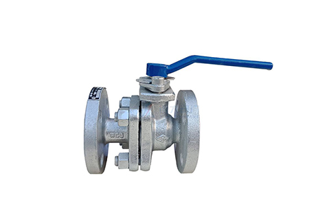
Forged Steel Ball Valve

Forged Steel Ball Valve

Forge Steel Globe Valve should consider the specific treatment of specific problems in the order of oil products in the future. In view of the different qualities of diesel and gasoline, the scour and decomposition ability of gasoline should be considered. In the future valve operation, when encountering gasoline section operations, replenish grease in time to prevent wear. When injecting grease, do not ignore the grease injection at the valve stem. There is a sliding sleeve or packing on the valve shaft, which also needs to be kept lubricated to reduce the frictional resistance during operation. If lubrication cannot be ensured, the torque will increase during electric operation and wear parts will be laborious during manual operation.

Some ball valves are marked with arrows. If there is no English FIOW writing, it is the direction of the seal seat, not as a reference for the flow of the medium, and the valve self-venting direction is opposite. Normally, a double-seat sealed ball valve has a bidirectional flow direction.

When maintaining the valve, pay attention to the water ingress in the electric head and its transmission mechanism. Especially in the rainy season the infiltration of rainwater. One is to rust the transmission mechanism or the transmission shaft sleeve, and the other is to freeze in winter. The torque is too large when the electric valve is operated, and the damage to the transmission components will cause the motor to be unloaded or the over-torque protection will trip and electric operation cannot be realized. The transmission parts are damaged and manual operation cannot be performed. After the over-torque protection is activated, the manual operation cannot be turned on and off. Forcible operation will damage the internal alloy parts.

Both steel and iron are alloys based on iron and carbon as the main additive element, collectively referred to as iron-carbon alloys.

The cast iron is smelted in an iron melting furnace to obtain cast iron (liquid), and the liquid cast iron is cast into castings, which are called cast irons.

What is the difference between cast steel and carbon steel. First, steel is classified by chemical composition

(1) Carbon steel: a. Low carbon steel (C≤0.25%); b. Medium carbon steel (C≤0.25~0.60%); c. High carbon steel (C≤0.60%).

Steel is classified according to the forming method: (1) Forged steel; (2) Cast steel; (3) Hot rolled steel; (4) Cold drawn steel.

Parameters of forged steel fully welded ball valve:

Nominal pressure: 150LB-2500LB

Applicable temperature: -29℃-200℃

Operation mode: manual, worm gear, electric, pneumatic, gas-liquid linkage, etc.

Scope of application: natural gas pipelines, heating, heating pipelines, long-distance petroleum, chemical pipelines

Use medium: water, natural gas, coal gas, chemical products, etc.

Manufacturing cycle: 8-10 days. Because the valve is made of forged steel, it must be customized, so the delivery time is relatively long

Application industry: Forged steel fully welded ball valves are widely used in: urban gas, urban heating, petrochemical, shipbuilding, steel, pressure regulating stations, power plants and other pipeline equipment

Features of forged steel fully welded ball valve:

1. The valve body adopts integral forgings to ensure that there will be no quality problems such as trachoma

2. Forged steel material manufacturing performance is more reliable, and there is no leakage through mechanical integral welding

3. The processing accuracy of the sphere is very precise and easy to operate. The sphere can be customized according to customer requirements

4. For the specific dimensions of the forged steel fully welded ball valve, customers can provide drawings and process them according to customer drawings

5. The valve seat is also composed of forgings, and the seal can be nylon, PPL, hard seal, etc., and the valve seal can be customized according to requirements

6. The forged steel fully welded ball valve has a longer service life than ordinary ones under the condition of correct selection, normal operation and maintenance. The number of switching times can reach tens of thousands of times, and the longest service life can reach more than 20 years.

Application fields of forged steel fully welded ball valve:

City gas: It is used as the main switch of the entire pipeline, especially in main lines and high-pressure pipeline networks.

Centralized heating: output pipelines, main lines and branch lines of large heating equipment.

Heat exchanger: The pipeline and each circuit are opened and closed, with a relatively small diameter.

Steel plant: various fluid pipelines, exhaust gas selective discharge pipelines, gas and heat supply pipelines, etc.

Various industrial equipment: various heat treatment pipelines, or main pipelines or high-pressure pipelines of some gas and gas companies.

2022年6月10日星期五

Globe valve types | Parts | Working principle |Advantages |Applications |Disadvantage | Body


A globe valve is a linear motion valve which is used to start,stop and regulate the flow of liquid in the pipeline.


It is not bidirectional valve.It is not used in either direction.


The disk did the work of starting,topping and regulating the flow of liquid.The disk has three positions :-

It can completely close the path

It can removed entirely from the path of flow.

In between valve seat and back seat for regulating the flow of liquid.


The disc of valve moves perpendicular to the seat as the valve opens and closes.


Globe valve working principle

The working principle of globe valve is that restricting the flow if liquid in pipeline by any obstruction material called disk.


When the handle wheel is rotated clockwise, steam and the valve plug move downward across the fluid flow line, and the valve plug is tightly located between the two valve seats. As a result, once the valve is completely closed, there will be no leakage of fluid through it.


When the handle wheel is turned anticlockwise, steam and the valve plug move upward across the fluid flow line, and the valve opens from its closed position, allowing fluid to flow through the globe valve.


How does a globe valve work ?

As we know that valve is used to regulate or shut off the fluid.A globe valve work the seat of the valve is in the middle of and parallel to the pipe, and the opening in the seat is closed off with the disk. When the handle is turned, manually or through an actuator, a disc is lowered or raised by means of the valve stem. The fluid flow is turned off when the disc is fully lowered


Globe valve parts

Globe valve parts list are following :-

1.Handwheel and nut :-Handwheel is fitted with threaded stem on top by a nut.The operation of valve is done by rotating handwheel clockwise or anti-clockwise.


2.Bonnet :-One of the outer globe valve parts that is connected to the body to provide a leak-proof closure is the bonnet. In different globe valves, different bonnet types such as bolted, screw-in, or union bonnet are used.


Each of these bonnet styles has its own set of benefits. The union bonnet, for example, not only adds strength to the body but is also ideal for applications that require regular cleaning or inspection. With its simple design, the screw-in bonnet provides a pressure-tight seal. The last type of bonnet is bolted bonnets, which are attached with bolts and are ideal for higher pressures.


3.Gland packing :-

Valve packing is a gasket that forms a tight seal between the valve stem and the bonnet. It’s used to keep liquids from leaking out of valve stems and stuffing boxes. The gland followers on most valves are tightened until the valve is leak-proof. Leakage occurs with loose packing; tight packing impairs valve movement and may cause stem damage.


Packing is available in a variety of materials, including PTFE, elastomers, fibrous material, and others. The valve packaging must be properly designed and manufactured in order to reduce the risk of stem damage and fluid leakage. On the other hand, it is important to keep in mind that over-tight packing can harm the stem.

A gasket is required for a reliable seal between the stem and the bonnet. This is known as packing. This consist of following components

1.Gland follower, a sleeve that compresses the packing after it has been compressed by a gland into the so-called stuffing box.

2.Gland was a type of bushing that compressed the packing into the stuffing box.

3.A stuffing box is a chamber that compresses the packing.

4.Packing is available in a variety of materials, including Teflon®, elastomeric material, fibrous material, and others.

5.A backseat is a seating arrangement located inside the engine compartment. When the valve is fully open, it creates a seal between the stem and bonnet and prevents system pressure from building up against the valve pakking. In gate and globe valves, back seats are frequently used

5.Seat ring :-The seat is one of components of globe valve that seal the space between the disk/stem and bonnet. The seat ring can be screwed into the valve or torqued. The seat, also known as a seat ring, offers a stable and replaceable shutoff surface. Seat rings can firmly secure the cage to the valve’s body.

6.Stem:-The valve stem is responsible for the proper positioning of the disk and provides the necessary movement to the disc, plug, or ball for opening or closing the valve.
The stem is a component of the globe valve that connects the disk to the handwheel or valve actuator in order to transmit the actuation force. It is one of the critical globe valve parts because it connects the actuator to the parts inside the globe valve. The stem of an actuator-controlled valve is smooth, whereas the stem of a manual valve is threaded.

The threaded ends of the smooth steam allow connection to the actuator and the plug. To prevent material from leaking from the valve, a wearable packing surrounds the smooth stem. As a result, during the maintenance period, the packing should be replaced on a regular basis. In the closure state, the stem can withstand a significant amount of compression force.

7.Disk:-One of the most important globe valve components is the plug or disk. It moves perpendicular to the seat and can either block or free the flow because it functions as a moveable physical barrier. When the valve is closed, the plug sits against the seat, blocking the flow, and when it sits above the seats, it allows the material to flow.

For globe valves, various disk arrangements have been designed, including composite type, ball type, and needle type. The composite disk has a better shut-off, whereas the ball type is used in low-temperature and low-pressure systems. When compared to the other two, the needle disk provides better throttling.

8.Body:-The valve’s body is the main structure that holds everything together. This section contains all of the internal parts of the globe valve that allow control of the substance that needs to be regulated. The body’s opening contains ports (usually two or three ports) that allow fluid to flow to the inside or outside of the globe valve.

9.Cage :-This cage is intended to encircle the stem and plug within the globe valve. The cage is one of the components that govern the flow within the globe valve. The flow can increase or decrease as the plug moves. The flow of the material inside the valve varies depending on the layout and design of the openings.


Cages are also responsible for guiding the plug to the seat to ensure a good shutoff.


What is a globe valve used for ?

globe valve used for regulation flow or pressures as well as complete shutoff of flow required.


Functions Of globe valve

A globe valve’s primary function is to start, stop, or regulate the flow. As the globe valve opens, the disk moves upward, allowing the fluid to flow proportionally. In an open position, the valve stem rises and pops out at the top. Globe valves are typically used in smaller sizes, usually 12 inches or less. The power required to operate a globe valve grows in proportion to its size. A globe valve is typically used as an on/off valve, but it can also be used for throttling.


Applications of globe valve

Globe valves are useful in a variety of applications where flow must be regulated but a constant flow of fluid is not required. Here are a few examples of common applications for globe valves:

1.Cooling water systems in which the flow must be regulated
2.A fuel oil system in which the flow is regulated and leaktightness is critical.
3.When leaktightness and safety are important considerations, use high-point vents and low-point drains.
4.Systems for feedwater, chemical feed, condenser air extraction, and extraction drain
5.Boiler vents and drains, as well as main steam vents and drains and heater drains
6.Seals and drains for turbines
7.Turbine lube oil system, among other things

Advantages and Disadvantages of globe valve

Advantages of globe valve

1. Shutoff capability is good.
2.Moderate to good throttling capability
Shorter stroke (compared to a gate valve)
3.Available in tee, wye, and angle patterns, each offering unique capabilities
4.Easy to machine or resurface the valve seats
5.With disc not attached to the stem, valve can be used as a stop-check valve


Disadvantage of globe valve

1.a greater pressure drop (compared to a gate valve)
2.To seat the valve, more force or a larger actuator is required (with pressure under the seat)
3.Throttling flow beneath the seat and shutoff flow above the seat


What is the difference between a globe valve and a gate valve?

One significant distinction between a gate valve and a globe valve is that a gate valve can be installed in multiple directions, whereas a globe v/v can only be installed in one direction.

A gate valve should only be installed where it can be fully opened and shut, and it should not be overtightened as this may cause the gate to distort.

A gate valve can be used to start and stop flow, but it cannot regulate the flow level.


2022年6月7日星期二

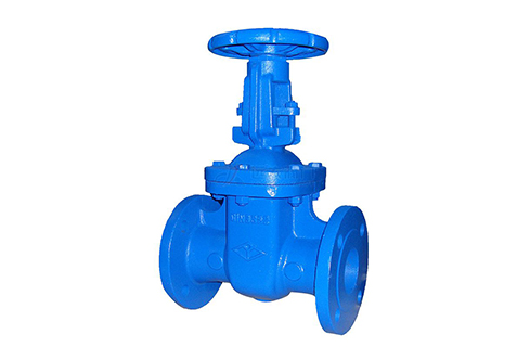
Understanding Valves: Globe Valves and Gate Valves


Structurally


When the installation space is limited, please pay attention to the selection:

The Cast Iron Gate Valve can be tightly closed with the sealing surface depending on the medium pressure, so as to achieve the effect of no leakage. When opening and closing, the valve core and the sealing surface of the valve seat are always in contact and rub against each other, so the sealing surface is easy to wear. When the gate valve is close to closing, the pressure difference between the front and rear of the pipeline is large, which makes the sealing surface wear more serious.

The structure of the gate valve will be more complicated than that of the stop valve. From the appearance point of view, the gate valve is taller than the stop valve and the stop valve is longer than the gate valve in the case of the same caliber. In addition, the gate valve can be divided into bright rod and dark rod. The shut-off valve does not.


Working principle


When the shut-off valve is opened and closed, the stem rises, that is to say, when the hand wheel is turned, the hand wheel will rotate and lift together with the stem. The gate valve rotates the hand wheel to make the valve stem move up and down, and the position of the hand wheel remains unchanged.

The flow rate is different, the gate valve is required to be fully open or fully closed, but the stop valve is not required. The shut-off valve has specified inlet and outlet directions, and the gate valve has no inlet and outlet direction requirements.

In addition, the gate valve has only two states: fully open or fully closed, the gate opening and closing stroke is large, and the opening and closing time is long. The movement stroke of the valve plate of the shut-off valve is much smaller, and the valve plate of the shut-off valve can be stopped at a certain place during the movement for flow adjustment. The gate valve can only be used as a cut-off and has no other functions.

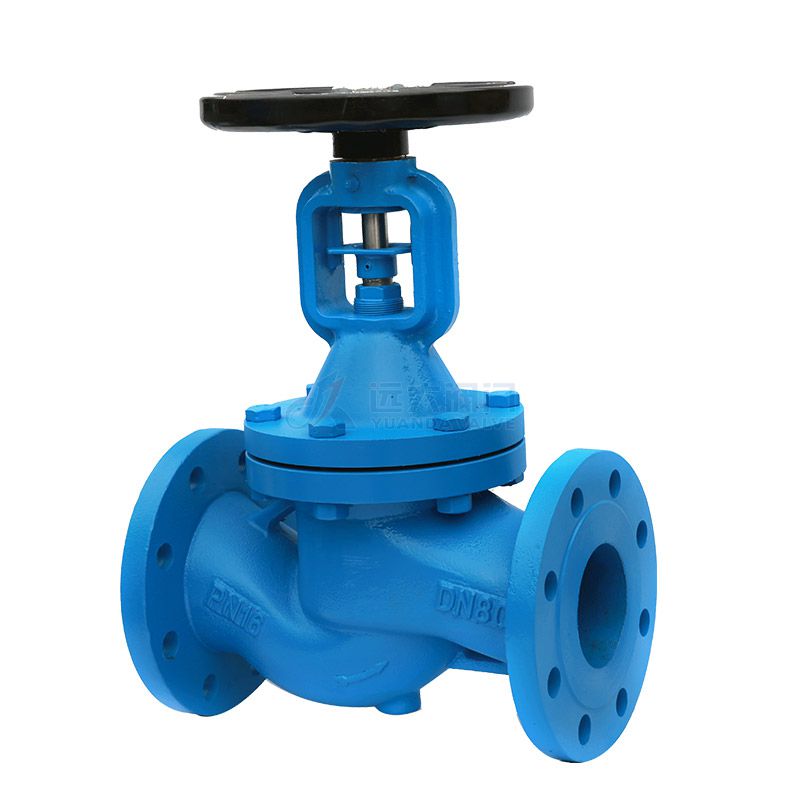
Cast Iron Gate Valve

Cast Iron Gate Valve


Performance difference


The shut-off valve can be used for cut-off and flow regulation. The fluid resistance of the stop valve is relatively large, and it is more laborious to open and close, but because the distance between the valve plate and the sealing surface is short, the opening and closing stroke is short.

Cast Iron Gate Valve China can only be fully opened and fully closed. When it is fully opened, the medium flow resistance in the valve body channel is almost zero, so the opening and closing of the gate valve will be very labor-saving, but the gate distance The sealing surface is far away and the opening and closing time is long.


Installation and flow


The effect of the gate valve in both directions is the same. There is no requirement for the inlet and outlet directions for installation, and the medium can flow in both directions. The stop valve needs to be installed in strict accordance with the direction indicated by the arrow on the valve body. There is also a clear stipulation regarding the direction of the inlet and outlet of the stop valve. The "Three Chemicals" of the valve in my country stipulates that the flow direction of the stop valve is from top to bottom.

The shut-off valve is low in and high out. From the outside, it is obvious that the pipeline is not on the horizontal line of one phase. The gate valve flow path is on a horizontal line. The stroke of the gate valve is larger than that of the stop valve.

From the perspective of flow resistance, the flow resistance of the gate valve is small when fully opened, and the flow resistance of the load stop valve is large. The flow resistance coefficient of ordinary gate valve is about 0.08~0.12, the opening and closing force is small, and the medium can flow in two directions. The flow resistance of ordinary globe valves is 3-5 times that of gate valves. When opening and closing, it needs to be forced to close to achieve the seal. The valve core of the stop valve does not contact the sealing surface when it is completely closed, so the wear of the sealing surface is very small. Because the main force of the flow is large, the stop valve that needs an actuator should pay attention to the torque control mechanism Adjustment.

There are two ways to install the shut-off valve. One is that the medium can enter from below the valve core. The advantage is that the packing is not stressed when the valve is closed, which can prolong the service life of the packing and can bear pressure before the valve. Under the circumstance, the packing should be replaced; the disadvantage is that the driving torque of the valve is relatively large, which is about 1 times that of the upper flow, the axial force on the valve stem is large, and the valve stem is easy to bend.

Therefore, this method is generally only suitable for small-diameter stop valves (below DN50). For stop valves above DN200, the medium flows in from above. (The electric shut-off valve generally adopts the way that the medium enters from above.) The disadvantage of the way that the medium enters from above is just the opposite of the way to enter from below.


Sealed


The sealing surface of the China Cast Iron Globe Valve is a small trapezoidal side of the valve core (see the shape of the valve core). Once the valve core falls off, it is equivalent to closing the valve (if the pressure difference is large, of course the valve is not tightly closed) , But the non-return effect is good), the gate valve is sealed by the side of the valve core gate plate, the sealing effect is not as good as the stop valve, and the valve core will not be closed like the stop valve.

2022年6月1日星期三

What Are the Commonly Used Check Valves?

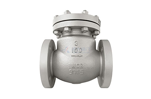
Check valve is also called one-way valve or check valve, its function is to prevent the medium in the pipeline from flowing back. The bottom valve of the pump to close the water is also a check valve.

The valve that opens or closes on its own by the flow and force of the medium to prevent the medium from flowing back is called a check valve. Check valves belong to the category of automatic valves, which are mainly used in pipelines where the medium flows in one direction, and only allow the medium to flow in one direction to prevent accidents.

Cast iron check valves are divided into three types: lift check valves, swing and lift check valves and butterfly check valves. Lift check valves can be divided into two types: vertical check valves and horizontal check valves. Swing check valves are divided into three types: single-leaf check valve, double-leaf check valve, and multi-leaf check valve. The butterfly check valve is a straight-through check valve. The above-mentioned check valves can be divided into three types in connection form: threaded check valve, flanged check valve, and welded check valve.

The installation of the check valve should pay attention to the following: 1. Do not make the check valve bear weight in the pipeline, and the large check valve should be independently supported so that it is not affected by the pressure generated by the piping system. 2. When installing, pay attention to the direction of medium flow should be consistent with the arrow direction of the valve body. 3. Lifting vertical flap check valve should be installed on the vertical pipeline. 4. Lifting the horizontal flap check valve should be installed on the horizontal pipeline.

Nominal pressure or pressure level of check valve: PN1.0-16.0MPa, ANSICLASS150-900, JIS10-20K Nominal diameter or caliber: DN15~900, NPS1/4~36 Connection method: flange, butt welding, thread, bearing Suitable temperature for plug welding: -196℃~540℃ Valve body material: WCB, ZG1Cr18Ni9Ti, ZG1Cr18Ni12Mo2Ti, CF8 (304), CF3 (304L), CF8M (316), CF3M (316L), Ti. Different materials are selected, and the check valve can be applied to various media such as water, steam, oil, nitric acid, acetic acid, oxidizing medium, urea, etc.

One. Use of wafer check valve:

The check valve is installed in the pipeline system, and its main function is to prevent the medium from flowing back. The check valve is an automatic valve that depends on the pressure of the medium to open and close. The wafer check valve is suitable for various pipelines with nominal pressure PN1.0MPa~42.0MPa, Class150~25000; nominal diameter DN15~1200mm, NPS1/2~48; working temperature -196~540℃, used to prevent The medium flows back. By selecting different materials, it can be applied to a variety of media such as water, steam, oil, nitric acid, acetic acid, strong oxidizing media, and uric acid.

Two. The main material of the wafer check valve:

There are carbon steel, low-temperature steel, duplex steel (F51/F55), titanium alloy, aluminum bronze, INCONEL, SS304, SS304L, SS316, SS316L, chromium-molybdenum steel, Monel (400/500), 20# alloy, Hastelloy, and other metal materials. The use and structural characteristics of the wafer check valve

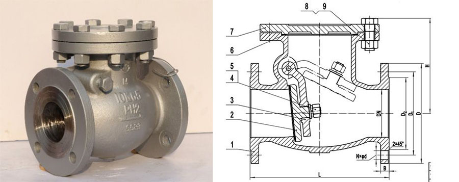
Swing and Lift Check Valves

Swing and Lift Check Valves

Three. Standards and specifications of wafer check valve:

1. Design and manufacturing: API594, API6D, JB/T8937, JB/T3595,

2. Structure length: API594, API6D, DIN3202, JB/T8937, ANSI/ASMEB16.10

3. Pressure and temperature rating: ANSIB16.34, DIN2401, GB/T9124, HG20604, HG20625, SH3406, JB/T74

4. Test and inspection: API598, JB/T9092, GB/T13927

5. Piping flange: JB/T74~90, GB/T9112-9124, HG20592~20635, SH3406, ANSI/ASMEB16.5, DIN2543-2548, GB/T13402, API605, ASMEB16.47

Four. The structural characteristics of the wafer check valve:

1. The structure length is short, and its structure length is only 1/4~1/8 of the traditional flange check valve

2. Small size and lightweight, its weight is only 1/4~1/20 of the traditional flange check valve

3. The valve flap closes quickly and the water hammer pressure is small

4. Both horizontal pipes and vertical pipes can be used, easy to install

5. Unobstructed flow path and low fluid resistance

6. Sensitive action and good sealing performance

7. The disc has a short stroke and a small closing impact

8. The overall structure is simple and compact, and the appearance is beautiful

9. Long service life and reliable performance

The role of the check valve in the pump water supply system is to prevent the impact of the high-pressure water backflow on the pump impeller. When the system is running for some reason, when the pump suddenly stops running, the pressure in the pump disappears, and the high-pressure water connected to the outlet of the pump will flow back to the pump in the reverse direction. When the pump outlet is equipped with a check valve, it will be closed immediately to prevent the high-pressure water from flowing back to the pump.

The cast steel Check Valve is an automatic valve whose main function is to prevent the backflow of the medium, prevent the pump and drive motor from reversing, and release the container medium. Check valves can also be used to supply pipelines for auxiliary systems whose pressure may rise above the system pressure. The main function of the check valve is to prevent the medium in the pipeline from flowing back. The opening and closing parts are opened or closed by themselves by the force of the flowing medium. The check valve is only used in the pipeline where the medium flows in one direction to prevent the medium from returning to prevent accidents.

Are Globe Valves Good for Flow Control?

  https://www.yuandavalves.com/globe-valve-wholesale/ When it comes to regulating and controlling fluid flow, choosing the right valve is cr...