2022年5月25日星期三

Symptoms of Valve Failure and How to Prevent It?

Valve failure can cause catastrophic damage to any vessel or system. However, detecting the first symptoms and preventing valve failure can help avoid such situations.

To help you understand the symptoms of valve failure and how to prevent it, Cast Iron Check Valve Supplier shares this article for you.

Why the valve failed

Symptoms of malfunctioning valves Valves are carefully designed devices designed to ensure safety and normal operation. Having said that, valve failure is still common.

According to flow control, many factors cause valve failure, including:

Abrasion of elastomer and valve seat gasket

Debris in the pipeline

Operate in a high-temperature environment

Improper valve installation, maintenance, and assembly

Symptoms of check valve failure

A faulty valve will give a warning signal when it fails. For example, when something goes wrong, a failed check valve will start to vibrate and even lose some internal parts. Other symptoms of check valve failure include backflow, excessive wear, and damage to components.

Noise can also be emitted when the check valve starts to fail. This situation is called "water hammer" and is caused by the disc hitting the valve seat. Water hammer can cause pipe rupture and severe damage. To alleviate this problem, it is recommended to install a quick-closing check valve to prevent pressure fluctuations.

When the valve starts to rupture, it will also start to stick and leak. When the valve is stuck in a certain position, it will jam, and when the debris enters the valve disc and valve body hole, it will jam. Leakage stems from damaged valve seats or discs or contaminants in the pipeline.

Preventive maintenance

Symptoms of malfunctioning valves As mentioned earlier, malfunctioning valves can severely damage the system and containers. However, the following preventive maintenance tasks can help prevent failures and extend the life of each valve.

Keep the valve clean

Contaminants and debris in any system can cause valve problems and failures. Keeping the pipeline clean is one of the easiest and most effective ways to prevent this.

To prevent debris from entering the system, please install filters and covers inappropriate places. For liquid systems, flushing pumps can also help keep the system clean. Flush before shutting down to minimize the accumulation of contaminants.
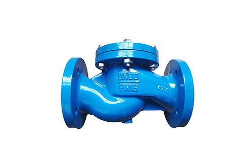
Cast Iron Check Valve

Cast Iron Check Valve

Lubrication valve

Use appropriate lubricants for valves to enhance performance and ensure correct operation. Also, make sure to relubricate regularly to extend the life of each valve and the system it uses.

Use the valve as directed

The most important precaution is to ensure that the valve is used correctly. For example, it is vital to ensure that each valve is installed and maintained correctly. Most importantly, choosing the right valve for each application will help prevent damage and valve failure.

Replace the valve as needed

Finally, the Cast Iron Check Valve needs to be replaced regularly to ensure optimal operation and safety. Therefore, once the valves in the system begin to show signs of failure, it is best to replace them with new parts immediately. Otherwise, it will cause the final system failure.

2022年5月20日星期五

WHY USE A BALL VALVE VERSUS A GATE VALVE?

With so many different types of valves on the market today, it can be difficult to decide which valve is most suitable for your application. In this article, Yuanda explores the merits of ball valves versus gate valves.


Selecting the best valve can make or break your system. Ball valves and gate valves are both designed to restrict and control flow. Which gives better longevity and leak prevention though? Read on to find out.


WHAT IS THE MAIN DIFFERENCE BETWEEN BALL AND GATE VALVES?

Ball and gate valves essentially perform the same function. However, their structural qualities are markedly different. Ball valves have a stem and ball, which turn horizontally, and are commonly referred to as “rotational” valves. They are best suited to applications requiring on/off control without pressure drop.


Gate valves open by lifting a round or rectangular gate (or wedge) out of the path of the fluid. The sealing surfaces between the gate and seats are planar, so gate valves are often used when a straight-line flow of fluid and minimum restriction is needed.


HOW DOES A BALL VALVE WORK?

Ball valves are designed with a ball inside the valve. A ball valve is a form of quarter-turn valve which uses a hollow, perforated, and pivoting ball (called a “floating ball”) to control flow through it. It is open when the ball’s hole is in line with the flow and closed when it is pivoted 90-degrees by the valve handle. The handle lies flat in alignment with the flow when open, and is perpendicular to it when closed, making for easy visual confirmation of the valve’s status.


WHICH IS BETTER: BALL VALVES OR GATE VALVES?

Ball valves are durable, performing well after many cycles, and reliable, closing securely even after long periods of disuse. These qualities make them an excellent choice for shutoff applications, where they are often preferred to gates and globe valves. That said, they do lack fine control in throttling applications.


Although ball valves tend to cost slightly more than gate valves of comparable quality, the minimal saving is not worth the potential issues that are likely to follow. Moreover, ball valves seal much tighter – and are therefore much less prone to leaks – than gate valves because of their 100 percent shut-off characteristics. Ball valves offer greater longevity, and a lower rate of failure, and are easier to use than gate valves.


Advantages and Disadvantages

Due to the differences in operation and design between gate valves and ball valves, both have certain advantages and disadvantages. Depending on your application, one is usually better than the other. Check out our table below to learn the key differences between gate and ball valves.


Ball valve

Gate valve

Shut off mechanism

Fast shut-off with only a quarter turn (90° turn) to close the valve.

Slow shut off as it requires more than a 360° turn to shut off the valve.

Water hammer

Fast opening and closing may cause water hammer.*

Slow opening and closing reduces the risk of water hammer.*

Visual detection

Open or closed state of valve can be visually detected with position of the handle.

Difficult to detect the open or closed state of valve.

Cost

Typically more expensive than a gate valve of the same specifications.

Typically cheaper than a ball valve of the same specifications.

Installation space

Requires more space than a gate valve to accommodate for quarter turn handle.

Requires relatively less installation space than a ball valve.

Size

Better suited for bore sizes below 2".

Better suited for bore sizes above 2".

Leakage

Provides tight seal even if used after a long period of time.

More prone to leaks than a ball valve.

Durability

Durable and less prone to damage

Valve stem can be prone to corrosion making the valve less durable.

If the flow is abruptly stopped by rapidly shutting off the valve, pressure builds up due to the momentum of the moving medium and this causes a short pressure surge. The pressure surge causes a noise which sounds like the pipes were struck by a hammer. A powerful water hammer can cause a rupture or leak in the system. 


China top valves supplier-Yuanda manufacture cast iron,Stainless Steel,Cast Steel,Flanged,ANSI,DIN,API,GOS Valves,Such as GOST Gate Valve,Angle Globe Valve,Motorized and Trunnion Ball Valve,Wafer Butterfly Valve,Swing and Lift Check Valve,Y Strainer,etc.

2022年5月17日星期二

Solve the problem of reducing valve in city water supply

(1) keep dirt and sundries away from the pressure-reducing valve pressure relief guarantee system. Newly built or revamped pressure relief system pipe network, is likely to leave sand, hemp, debris. Before putting into operation, generally should carry on the water flushing, after meeting the cleaning requirements, install the pressure reducing valve and filter core, so as to avoid sundries into the pressure reducing valve, reducing valve core phenomenon. After the system enters the work, it is closely related to the flow capacity of the filter set on the system to ensure the smooth flow of the pressure relief system. If the filter element is seriously adsorbed by sundries, it will affect the work of the pressure reducing valve. Therefore, it is necessary to conduct regular inspection on the filter to timely pollute. Practice shows that this work is carried out every 2 to 3 months, and some adjustable (spring-type, thin-film) pressure-reducing valves, the main valve or pilot valve itself to set a filter, also need to regularly disassemble and wash the filter element.

(2) the pressure-reducing valve China set prepared by 1 should be rotated regularly. Most of the high - rise building water pressure relief valve pressure relief support system, is set up in the vertical water supply, generally located on the main water supply area. Considering the water reliability of many users (the residential area has dozens to hundreds of households, public buildings such as hotels, restaurants, each area has dozens of rooms... ), pressure reducing valve shall be installed side by side in design (1 for 1). The pressure relief channel is equipped with gate valve or butterfly valve on both sides, which can open and close any pressure relief channel. In order to make the parallel two sets of pressure relief valve channels work normally, it is routine to exchange once a month, and the pressure relief channel remains stagnant water and scale, and the valve core of pressure relief element will be stuck and fail.

Valve Supplier China

Upon the arrival of the water supply pressure-reducing valve China set, preliminary acceptance of the valve set components shall be conducted in accordance with the design requirements. The preliminary acceptance inspection shall be conducted jointly by the construction unit and the on-site project supervisors.

The preliminary acceptance of the solution of the pressure reducing valve fault in urban water supply shall include the following contents:

1. The model, specification and performance parameters of valve assembly should be consistent with the design requirements;

2. The components, accessories and spare parts of the pressure-reducing valve group should be complete;

3. The inspection report, qualification certificate, quality guarantee certificate and other technical data of the pressure-reducing valve group should be complete;

4. For domestic water supply system or direct drinking water pipeline system, the water supply pressure-reducing valve group shall have a copy of the type inspection of provincial or above quality, sanitary supervision and inspection institution and the sanitary inspection report of water-related products, and shall be stamped with the seal of the manufacturer;

5. The installation and operation instructions and supply list of valve assembly components should be complete;

6. Valve assembly package intact, appearance without defect and bruise;

7. If necessary, it may entrust relevant departments to conduct on-site sampling reinspection.

2022年5月12日星期四

Pneumatic control valve debugging

Pneumatic control valve debugging by valve supplier.

Pneumatic Drive Type Butterfly Valve before use, focus on the spring preload, neutral point, E/P converter, locator, etc., to meet the valve stroke, valve displacement linear, switching time, leakage and other performance indicators. Before commissioning, (1) the process pipeline must be purged strictly; (2) the handwheel mechanism should be in the "release" position; (3) check whether the pressure of reducing valve air supply meets the gas supply requirements.

1. BenchSet adjustment method

To prevent the valve from closing or opening, the actuator must be adjusted before it is installed into the valve body.

According to the upper and lower limits of pre-tightening force required by the valve nameplate, a simple special adjustment tool is used to adjust the initial spring force.

Open and close the valve several times by inflating the exhaust to ensure smooth movement of the pneumatic head.

Press the pneumatic head, record the pressure just moved by the pneumatic head connecting rod and compare it with the lower limit of pre-tightening force on the valve nameplate, adjust the spring pre-tightening force adjusting nut until the pressure reading when the pneumatic head connecting rod just moved is the lower limit.

Continue to increase the pressure to the upper limit and mark the stem as the pneumatic head link moves to the end of the body.

Slowly pneumatic air pressure drop back to the lower limit value, record the valve stem tags, the distance to the pneumatic head end of the connecting rod with the valve nameplate schedule is consistent, if consistent, adjusting spring pre-tightening force and prove that the valve closed or open enough force in natural state, or need to replace the spring, reinstall and according to the above steps to carry on the adjustment of the pre-tightening force.

2. Setting of NEUTRALPOINIT

The neutral point is that the handwheel is adjusted to the position that does not affect the automatic adjustment. It may be a point or an area. Too high a neutral point will cause internal leakage, and too low a setting will easily lead to insufficient flow. Usually valve isolation or automatic failure, often by destroying the neutral point of pneumatic control valve to achieve the valve fully open, fully closed or maintain a certain degree of opening. Usually have only need to handle the neutral point of roller skating piece of the neutral point of a pointer on the scale on the neutral line, also can be adjusted by hand ", loss of air pressure to open the pneumatic valve "neutral point set, should make the pneumatic valve in a loss of air pressure, full open position the handwheel clockwise in the direction of the clearance of rotating until feel resistance under the instructions manual lever to guide bush check, and then counter-clockwise 1/2 circle rotate in the direction of the open"; Set the neutral point of the pneumatic valve in the direction of deaeration and turn the handwheel counterclockwise to the open direction until the resistance is felt, indicating that the manual rod reaches the stop position of the guide sleeve, and then rotate 1/2 turn clockwise to the direction of the close. Adjust to the neutral point position with the hand wheel lever lock lock.

3. Check electrical converter (E/P)

The current source is used to provide 4mA ~ 20mA dc current signal, and the SAR provides compressed air.

Take the positive action pneumatic control valve as an example to carry on the following adjustment, its output pressure must meet the precision requirements.

Zero adjustment, input 4mA current signal, turn the zero adjustment screw to read the pressure gauge data until the output pressure is 20kPa.

Adjust range, input 20mA current signal, adjust range adjustment screw until output pressure 100kPa.

Linear check, input 8, 12, 16mA, output pressure is 40, 60, 80kPa.

Repeat until the precision requirement is met.

4. Check valve positioner

Take the pressure signal of 20kPa ~ 100kPa from E/P converter as the input signal of the locator. First open the air source of the locator to check the smooth operation of the locator.

Adjust the input signal to half of the range, open the air source, then the locator rotating arm should be in the horizontal position, the valve should be 50% open, otherwise check whether there is a leak or whether the locator CAM installation is proper.

Adjust zero so that the positioner is entered at zero, loosen the nozzle lock screw, and adjust the nozzle until the valve corresponds to the fully closed (or fully open) position.

Adjust the range so that the positioner input is full, adjust the position of nozzle baffle, so that the valve corresponds to the full open (or closed) position.

Check whether the valve meets the requirements of 0%, 25%, 50%, 75% and 100% opening at the input pressure of 20, 40, 60, 80 and 100kPa respectively, or make repeated adjustment.

2022年5月8日星期日

Failure Analysis and Treatment of Stainless Steel Bellows Globe Valve

1. Use the stainless steel bellows stop valve to install on the pipeline of the ship's power plant. During the use of the valve, leakage at the valve stem and rust of the valve stem occurred, although it has been repaired. But the problem recurred. After analyzing the cause of the failure, a suitable solution was adopted to eliminate the failure and ensure the performance of the valve.

2. Problem analysis

Bellow Seal Globe Valve leakage is generally divided into internal leakage and external leakage. There are many reasons for leakage. Endocrine is generally due to the failure of the sealing surface caused by the liquid medium containing solid impurities. Combined with the analysis of the on-site usage, the reason for the leakage of the valve stem is mainly related to the valve structure, working environment and operation mode.

2.1 Structure

The valve stem adopts a double sealing structure of bellows and packing. The bellows are welded with the inner lining ring and the outer lining ring to form a bellows assembly and then welded with the valve stem and the guide body to block the leakage of the medium through the valve stem. The valve stem moves up and down from the flat key I upwards until the upper-end surface of the flat key I contacts the lower end surface of the lower packing. Because the lower packing is made of PTFE material, if the valve is opened too much, the flat key I will be embedded in the packing, the valve can no longer be opened and closed, and the bellows assembly will be killed, causing the medium to leak along the valve stem. The stretched length and compressed amount of the bellows are determined according to the stroke of the valve. If the stretch or compression exceeds the limit, the bellows may be damaged, causing the small pipe to rupture and seal failure. Therefore, it is necessary to increase the limit device for opening and closing the valve, so that the bellows always expand and contract within the design range during the opening and closing process of the valve.

2.2 Working environment

The harsh working environment of the carbon steel stainless steel globe valve is also a cause of its failure.

Because the Carbon Steel Stainless Steel Globe Valve installed in the ship body has been working in a salt spray environment for a long time, and there is often condensation dripping on the upper part, causing corrosion of the upper thrust ball bearing, and in severe cases, contact with the valve stem corrosion

2.3 Operation

If the bellows stop valve is opened or closed excessively during use, the valve may not meet the relevant performance requirements. When the valve is closed excessively, the sealing surface may be crushed, causing the seal to fail when the valve is used again. When the valve is opened excessively, the bellows assembly may be operated, causing the valve to leak.

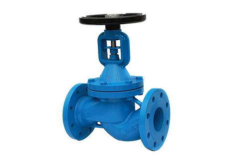
Bellow Seal Globe Valve

Bellow Seal Globe Valve

3. Improve

After analyzing the problems of the valve, the structure, operation, and environment were improved. The first is to increase the limit welfare fee of the flat key I and add a 3mm thick stainless steel packing pad to the lower packing of PTFE material to prevent the packing from getting dirty and restrict the valve stem.

When the valve is closed, if the valve cannot be shut off, it should not be forced to close. Instead, the valve should be opened, washed with fluid for a period of time and then closed again. If it still cannot be closed, check the ground sealing surface. When the valve is opened, when the valve is opened to a certain height, after the valve stem encounters a small resistance, try not to continue to force it to extend the life of the valve stem and its sealing components. For the stop valve with thrust ball bearing on the upper part of the valve stem, during installation, try to avoid the direct drip of condensed water on the valve and cause the valve stem to rust.

4. Conclusion

After the improvement of the bellows stops the valve, there is no recurrence of bellows cracking, valve stem rusting and leakage, etc., and it is in good condition.


2022年5月5日星期四

[Valve supplier] How to solve the regulator leakage problem?


Cast Iron Check Valve Supplier shares that regulating valves are the main type of actuators that change fluid flow  through dynamic operation by receiving control signals from the regulating  control unit. Control valves are generally composed of actuators and valves. If  according to its matching actuator power, control valve can be divided into  pneumatic, electric, hydraulic three. Below we say the control valve several  common faults and solutions.

In the modern factory automation control system, the control valve, as the  terminal actuator of the automatic control system, receives the control signal  to realize the adjustment of chemical process. Its motion sensitivity is  directly related to the quality of the regulating system. According to the  actual statistics on the scene about 70% of the fault from the control valve.  Therefore, the factors and countermeasures affecting the safe operation of  control valve are summarized and analyzed in daily maintenance.

The following analysis of several common leakage fault phenomenon, put  forward countermeasures.

Leaks in the valve

Uncomfortable stem length. Open valve, stem too long stem up (or down)  distance is not enough, resulting in a gap between the valve core and the seat,  not enough contact, resulting in lax closure and leakage. The same air off valve  stem is too short, resulting in a gap between the valve core and the seat, not  enough contact, resulting in lax closure and leakage.

Solutions:

Should shorten (or extend) the control valve stem to make the control valve  length appropriate, so that it is no longer internal leakage.

Packing leakage

After the packing is loaded into the packing box, axial pressure is applied  to it through the gland. The packing is plastic, causing radial force and close  contact with the stem, but this contact is not very uniform. Some parts are  loose, some parts are tight, and some parts are not touching at all. Control  valve in the use of the process, there is a relative movement between the stem  and packing, this movement is called axial movement. In the process of use High Temperature Ball Valves China, with  the high temperature, high pressure and strong permeability of the fluid medium,  the control valve packing box is also the location of leakage phenomenon more.  The main cause of packing leakage is interfacial leakage, and there will be  leakage for textile packing (pressure media leak outward along the tiny gap  between packing fibers). The interface leakage between the stem and the packing  is caused by the gradual attenuation of the contact pressure of the packing, the  packing itself aging and other reasons, at this time the pressure medium will  leak outward along the contact gap between the packing and the stem.

Solutions:

In order to facilitate packing loading, a metal protective ring with small  erosion resistance clearance is placed at the bottom of packing box to prevent  packing from being pushed out by medium pressure. Stuffing box each part and the  packing contact part of the metal surface to finish processing, in order to  improve the surface finish, reduce the packing wear. Flexible graphite packing  is chosen, because of its good air tightness, friction small, use for a long  time after the change is small, the wear loss is small, easy maintenance, gland  bolts to tighten, do't change after the friction pressure resistance and heat  resistance, good internal media, contact with the valve stem and gland internal  metal corrosion pitting or not. In this way, effectively protect the valve stem  packing box seal, and ensure the reliability and long-term packing seal.

Spool, valve seat deformation leakage

The main cause of spool and seat leakage is the strengthening of corrosion  caused by casting or forging defects in the production of control valves. And  corrosive medium through, fluid medium erosion can also cause the leakage of the  control valve. Corrosion mainly exists in the form of erosion or cavitation.  When the corrosive medium through the control valve, it will produce erosion and  impact on the valve core, valve seat material into an oval or other shape, as  time goes by, leading to the valve core, valve seat is not matched, there is a  gap, close lax leakage.

Solutions:

The key to the valve core, valve seat material selection, quality. Choose  corrosion - resistant materials, pitting point, trachoma and other defects of  the product resolutely removed. If the valve core, valve seat deformation is not  too serious, can be ground by fine sandpaper, eliminate traces, improve the  sealing smoothness, in order to improve the sealing performance. If the damage  is serious, it should be replaced with a new valve.

Are Globe Valves Good for Flow Control?

  https://www.yuandavalves.com/globe-valve-wholesale/ When it comes to regulating and controlling fluid flow, choosing the right valve is cr...